Event-Driven & Reactive Hardware
Past Software Makes Hardware chapters introduced a hardware abstraction ladder, including physical, structural, and behavioral layers. Here we'll dig into the common patterns at the behavioral layer - which will look surprisingly familiar to users of modern, asynchronous, concurrent environments such as NodeJs or Python's asyncio.
Behavioral hardware programming - or as chip-folks call it, hardware description - came into vogue around the mid 1980s. The industry's two most popular hardware description languages (HDLs), Verilog and VHDL, were both introduced in these early HDL days. While Verilog and VHDL both support the lower structural layer, their new contribution was the addition of the behavioral features described here. The general idea is that instead of directly programming a piece of hardware's structural content - essentially a hierarchical list of components and connections - designers can describe what a hardware block does, at a slightly higher level of abstraction.
Nearly every complex piece of digital hardware you use was written in either Verilog or VHDL. This includes essentially every chip required for reading this article -- your computer (or smartphone) CPU, the network interface transmitting and receiving this document, and the GPU rendering it on your screen.
These languages generally resemble a C++-ish level of abstraction and productivity. But HDLs centrally integrate a few programming paradigms which look, well, awfully shiny and new to a lot of programmers in 2019. Behavioral HDL code particularly features the event-driven and reactive patterns widely used in modern asynchronous environments.
There is good reason for this. Hardware is inherently "executing" in parallel; hardware "programs" therefore had to describe parallelism from day one. Worse yet, complex hardware is doing tons of things in parallel - not just dozens or hundreds, but thousands or millions. Mimicking that level of parallelism has generally required simulating it using concurrency. (If that statement seems self-contradictory, check out the popular talk Concurrency is Not Parallelism from Google's Rob Pike.)
As more software - and more really popular software - has become more concurrent, these concurrency patterns have seeped into the minds of more engineers.
Event-Driven Pattern
The event-driven paradigm can colloquially be described as something like:
- Stuff happens
- Code runs in response
Where the "stuff" happening can be described as a series of events. In a web environment, typical programmer-accessible events would include user interactions (clicks, keystrokes), timers, or the completion of slow asynchronous operations, such as file I/O or networking. Below the surface, more native events trigger things like timers and background housekeeping.
Popular asynchronous frameworks such as NodeJS and Python's asyncio (among the really popular software referenced earlier) execute asynchronous code in what is generally called an event loop. Application code dictates what events are added, and the background execution-engine sorts out when they are to execute, and runs them one at a time. Note that while these libraries can appear to use parallelism, most do not. The event-loop construct instead uses concurrency. NodeJS is particularly outspoken in its single-threaded-ness. Note no locks, semaphores, or other hallmarks of parallel-programming are generally required to use Node. (This has likely been a significant source of its immense popularity.)
Behavioral hardware simulation runs on a near-identical paradigm. Events typically come in the form of changes elsewhere in the system, often of signal values. HDLs include built-in syntax for capturing the sensitivity of a method -- or in HDL lingo, a procedural block -- to changes in signal values.
The event-driven pattern is commonly used to describe sequential logic, in which the outputs of a hardware module are functions of both the current inputs, and the module's current state. Most digital hardware is both sequential and synchronous, in that its operations are triggered by edges of a widely distributed timing signal, commonly called the clock. Finite state machines (FSMs) are among the most common examples.
module fsm ( /* ... */ )always @ (posedge clock or negedge reset)next_state = state;out = 0;case (state)A :if (in) next_state = C;else next_state = B;B :if (in) beginout = 1;next_state = C;endC :if (~in) beginout = 1;next_state = B;enddefault : beginout = 1’bX;next_state = 3’bX;endendcaseendendmodule
Even the most complicated pieces of digital silicon generally boil down to this pattern: sensitivity plus associated call-back code. Take an (excerpt of) an open-source RISC-V CPU implementation as an example.
module RISCVCPU (clock); // A RISC-V module excerptparameter LD = 7'b000_0011, // Instruction opcodesSD = 7'b010_0011,BEQ = 7'b110_0011,NOP = 32'h0000_0013,ALUop = 7'b001_0011;input clock;reg [63:0] PC;// ...integer i;initial beginfor (i=0; i<=31; i=i+1) Regs[i] = i;endalways @(posedge clock) begin// Fetch & increment PCIFIDIR <= IMemory[PC >> 2];PC <= PC + 4;IDEXA <= Regs[IFIDrs1];IDEXB <= Regs[IFIDrs2];// ...beginif ((opcode == LD) || (opcode == SD))beginALUOut <= A + ImmGen; // compute effective addressstate <= 4;endelse if (opcode == ALUop) begincase (IR[31:25]) // case for the various R-type instructions0: ALUOut <= A + B; // add operationdefault: ; // other R-type operationsstate <= 4;endelse if (opcode == BEQ) beginif (A == B) beginPC <= ALUOut; // branch taken--update PCstate <= 1;endelse// ...endend// ...endmodule
The core instruction-execution code begins just after the always @(posedge clock) annotation, and extends from the subsequent begin to its paired end (Verilog's scope delimiters). This core is, more or less, a big switch statement. Sort out the type of instruction to be executed, and run it. This looks a whole lot like common virtual-machine instruction-executors, such as CPython's evaluation loop:
PyObject * PyEval_EvalFrame(PyFrameObject *f) {PyObject **stack_pointer; /* Next free slot in value stack */int opcode; /* Current opcode */switch (opcode) {case TARGET(BINARY_OR): {PyObject *right = POP();PyObject *left = TOP();PyObject *res = PyNumber_Or(left, right);Py_DECREF(left);Py_DECREF(right);SET_TOP(res);if (res == NULL) goto error;DISPATCH();}case TARGET(LIST_APPEND): {PyObject *v = POP();PyObject *list = PEEK(oparg);int err;err = PyList_Append(list, v);Py_DECREF(v);if (err != 0) goto error;PREDICT(JUMP_ABSOLUTE);DISPATCH();}// ...
The Two Run-Times
By now you may be wondering, when does any of this HDL code run? Unlike typical software, behavioral HDL code operates in (at least) two essential runtimes:
- Logic Synthesis is the compilation of behavioral HDL code into lower level representation, usually logic gates.
- Think of this as the compiler. Although note the output language from this compiler is often the same as its input, i.e. Verilog. The output just uses the lower-level constructs and avoids the higher-level ones.
- Simulation is the runtime which predicts the hardware's behavior.
- Most of the behavioral constructs discussed here -- sensitivities, event loops, reactive updates, and the like -- apply to this simulation runtime.
- The model of digital simulation paired with these behavioral descriptions is called discrete-event simulation. It is used in a number of fields outside electronics, but is particularly pervasive here.
While we'll briefly touch on logic synthesis in a later section on reactive hardware, our primary focus is the discrete event simulation run-time.
Discrete-Event Simulation
Whether or not those piles of Verilog and C code make much sense, we can pretty quickly introduce the discrete-event simulation run-time, using a more designer-friendly language. EventSim (https://github.com/HW21/EventSim) is an open-source JavaScript implementation of these ideas.
https://github.com/HW21/EventSim
Events
First, we'll need to define what we mean by Events. For hardware simulation an Event minimally consists of:
- (a) A
task(function-object) to be run, and - (b) A simulated
timeto run it at
We'll use an ECMAScript 2015+ class to define these Events. For now, the Event-class won't have any behavior, just the two data members time and task.
class Event {/* Event "class"* Mostly a two-tuple or structure of* (a) A `task` (function-object) to be run, and* (b) A simulated `time` to run it at */constructor (time, task) {this.time = time;this.task = task;}}
Hardware Model
Next we'll need some sort of hardware model. We won't go through the heavy lifting of parsing an existing HDL - instead we'll create a model embedded in the same language as our simulation runtime: modern Javascript.
Looking back at the Verilog we've already seen, modules tend to be comprised of two categories of things:
- Structural content, including signals, ports, parameters, and instances of other modules.
- Procedural blocks, which describe the module's behavior, in code that runs procedurally from beginning to end. These look a lot like functions or class methods. Annotations on each procedural block (
always,initial, et al.) describe the sensitivities which will cause them to run.
These two categories look an awful lot like the classes of object-oriented languages such as Python or C++, or object-oriented-ish languages such as Javascript. We'll use such a JavaScript class to represent a sample hardware module.
class Module {/** A Simple System-Model,* Using the sorts of event-driven constructs common in Verilog or VHDL,* But calling `sim.add_event` instead of using special syntax.*/constructor () {// This "this binding" can go away if using arrow-function-enabled Javascriptthis.kickStart = this.kickStart.bind(this);this.keepGoing = this.keepGoing.bind(this);// Create our Sim object. This would be "behind the scenes" in a dedicated HDL.this.sim = new Sim();this.sim.add_event(new Event(0, this.kickStart));}kickStart () {console.log(this.sim.time.toString() + " KICK STARTING!");const e = new Event(11, this.keepGoing);this.sim.add_event(e);const e2 = new Event(3, this.keepGoing);this.sim.add_event(e2);}keepGoing () {console.log(this.sim.time.toString() + " STILL GOING!");const e = new Event(this.sim.time + 10, this.keepGoing);this.sim.add_event(e);}}
Our starter hardware-module-class skips many of the features and niceties of a dedicated HDL. There are no signals, ports, or module instances (for now). And there is no dedicated syntax for generating events. Instead the Module calls an add_event method on this.sim, its reference to its simulation run-time.
Simulation Run-Time
With all this groundwork in place, a basic simulation run-time turns out to be pretty straightforward. The most basic simulation has two data members:
- A current simulation
time - (Some sort of) store of future
events, often called the event queue
Next we'll sort out what data structure works best for storing and processing future events. There are a few helpful realizations to make here.
- First, the simulation run-time's causality contraint is that events are executed in non-decreasing simulation-time order. Events may be added to the queue in arbitrary order, but must be executed in the order of their simulation-time. In other words, we can think of the event loop as executing events by priority, and event-priority is dictated by minimum time.
- Second, while we need to be able to find the minimum-time event, the order of the remaining events is irrelevant. In principle we can maintain a fully sorted store of future events, but the majority of work required for sorting goes to waste. We don't care much whether the, say, 499th and 500th-priority future events are in order, especially knowing that the execution of the preceding 498 may add more events before or in-between them.
Conveniently there is a well-known, fast, widely popular data structure with exactly these features: the (minimum heap)[https://en.wikipedia.org/wiki/Heap_(data_structure)]. (Some introductions to the heap even use this use-case as an introductory example.) Nearly all popular languages have a robust implementation available in either built-in or widely popular external libraries. For our JavaScript implementation we'll use the collections package available from NPM.
With all these realizations in place, the Sim class implementing this runtime only needs three simple methods:
- A constructor, which initializes its primary data members
add_event, which we saw being used byModule, adds a (future) event to the queuerundoes the heavy lifting - running the simulation up to a specified timetstop
var Heap = require("collections/heap");class Sim {/* Discrete-Event Simulation Class */constructor () {// Our primary attribute is a min-heap, sorted by event-timethis.events = new Heap(null, null, function (a, b) { return b.time - a.time; });this.time = 0;}add_event(e) {/* Add new Event `e` */this.events.push(e);}run (tstop) {/* Run simulation, up to time `tstop` */while(this.events.length) {// Grab the next eventconst e = this.events.pop();// If it's after tstop, put it back and bailif (e.time > tstop) {this.events.push(e);break;}// Run it!this.time = e.time;e.task();}}}
That's it! We're ready to create a module-instance and simulate it.
// Create our model instanceconst model = new Model();const sim = model.sim;// Run for a whilesim.run(40);// Pause, look around a secondconsole.log("PAUSED!");// Now run for a while longersim.run(100);
Running EventSim’smain.jsscript, which includes all this code, generates output along these lines:
yarn run v1.15.2$ node --use_strict main.js0 KICK STARTING!3 STILL GOING!11 STILL GOING!13 STILL GOING!21 STILL GOING!23 STILL GOING!31 STILL GOING!33 STILL GOING!PAUSED!41 STILL GOING!43 STILL GOING!51 STILL GOING!53 STILL GOING!61 STILL GOING!63 STILL GOING!71 STILL GOING!73 STILL GOING!81 STILL GOING!83 STILL GOING!91 STILL GOING!93 STILL GOING!✨ Done in 0.12s.
Reactive Pattern
In reactive programming, a piece of software describes static relationships between input and output quantities, which continue to hold even when the input quantities change. The reactive style is quick to illustrate through a comparison with the more common imperative style. In either, we can imagine setting three variables like so:
a = 1b = 2c = a + bc
3
Imperative and reactive styles differ when the values of a or b are changed - after the assignment to c. In the typical imperative pardigm, the value of c is unchanged:
a = 11c
3
The imperative assignment statement c = a + b refers to the values of a and b, now -- at the time of the assignment.
In the reactive pattern, assignment means something quite different -- essentially that c should hereby equal the sum, of a and b, forever.
a = 1b = 2c = a + bc
3
a = 11b = 22c
33
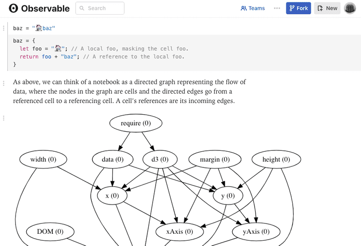
This is a fairly different idea of what assignment means. Mapping the reactive pattern onto typical imperative languages requires (somehow) updating the value of c "in the background", whenever its dependencies change value. This requires something like a dependency graph between variables, and a set of update methods called when an input variable changes value. Conveniently these update-routines are well-suited to be run from something like the event loop introduced in our prior section.
Popular implementations of the reactive pattern include the Observable Notebook, which uses JavaScript for a combination of web programming and visualization. Perhaps everyone’s least favorite reactive programs are Excel spreadsheet formulas. Data is free to change well after formulas are entered; in fact this is generally the point.
Reactive Hardware
Although implementing the reactive pattern in imperative languages requires a bunch of background machinery, it maps super-cleanly onto hardware. The pairing is so natural that reactive assignment is built directly into most popular HDLs. Verilog uses an assign keyword to make reactive, or in its lingo, continuous assignments.
module combinational (input a, b, c, d, output o);assign o = ~((a & b) | c ^ d);endmodule
These reactive assignments map directly to combinational circuits, that is, logic in which the outputs are functions solely of the current state of the inputs. For the Verilog example above, we can imagine a synthesis program mapping to a logic circuit like so:
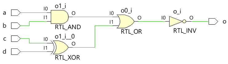
A reactive assignments conveys something very similar to the instantiation of, say, an AND gate: the output shall equal the AND function between its inputs, not just at the time of assignment, but at all times. The primary utility of the HDL code is in providing a platform-independent (or in chip terms, process technology-independent) description of this set of logic. Like other compilers, logic synthesis generally requires two primary inputs:
- An input program to be compiled, and
- A target environment to compile it for
For a typical software compiler, the target environment is generally the underlying platform: ARM or x86 instructions, Java or Python virtual-machine byte-code. For hardware synthesis, in contrast, the target environment comprises a logic cell library, generally designed for a specific process technology. Unlike the software compiler, this will often also include a set of implementation constraints, for example on the target speed or size.
Reactive HDL assignments enable a target-independent description of the hardware “program” to be compiled. We can imagine the combinationalmodule being usable in TSMC 16nm FinFET, decades-old 1µm, and every process technology in between.
While the reactive pattern is powerful for this platform-independent description of combinational logic, it remains a fairly low-level behavioral description. Reactive assignments can capture the combinational relationships between hardware signals, but have no means of incorporating the state, or history, of the system. This is where the event-driven descriptions typically come in.
"High-Level" Hardware Description
The hardware-programming styles we've introduced so far generally resemble a C++-ish level of abstraction and productivity. The most elaborate of these facilities (behavioral procedures, platform-independent modules) were introduced with the industry's primary HDLs (Verilog and VHDL) in the mid 1980s. In 2019, nearly every complex piece of digital hardware is still written in either Verilog or VHDL. In over three decades of their lifetime, no consensus has emerged in the hardware community on how to raise the level of designer productivity to mirror that of modern, programmer-centric software languages.
The initial, and perhaps still most prevalent, efforts use a set of scripting languages (Perl, Bash, or TCL) to generate Verilog or VHDL. (A particularly popular and SAD! such house-of-cards is built of emacs macros.)
More recently, two competing approaches to improving hardware productivity have emerged. The first, generally referred to as High-Level Synthesis (HLS), refers to a set of tools and techniques which attempt to describe hardware functionality in a relatively low-level software language such as C++, removing all of the hardware abstractions such as modules, ports, signals, and wires. HLS dramatically elevates the level of hardware abstraction - effectively removing it altogether -- without materially changing the abstraction level of the description language.
A newer and contrasting approach, primarily borne from academia, uses modern hardware-description libraries built atop existing programming languages. These modern HDLs near universally eschew HLS, and in many cases drop the event-driven behavioral paradigm. Modern HDLs instead focus on using high-productivity programming language facilities to manipulate structural hardware descriptions, perhaps incorporating the reactive, continuous assignments at the bottom of the behavioral hardware modeling spectrum.
To date the most accomplished modern HDL is Chisel, developed at UC Berkeley. Chisel is embedded in Scala, and uses a combination of object-oriented and functional programming to craft structural-level hardware.
import chisel3._class GCD extends Module {val io = IO(new Bundle {val a = Input(UInt(32.W))val b = Input(UInt(32.W))val e = Input(Bool())val z = Output(UInt(32.W))val v = Output(Bool())})val x = Reg(UInt(32.W))val y = Reg(UInt(32.W))when (x > y) { x := x -% y }.otherwise { y := y -% x }when (io.e) { x := io.a; y := io.b }io.z := xio.v := y === 0.U}
Chisel has been reported as being used at Google, in the design of their Edge TPU chip. Other modern HDLs include MiGen, Cornell's PyMtl, Stanford's Magma, all based in Python, and SpinalHDL, based in Scala. All are even earlier-days, and have seen little commercial deployment.
Should I Care?
Few software engineers will have good reason to learn Verilog or VHDL. (Hopefully soon enough, few hardware engineers will have reason to learn them either.) But several trends are making hardware programming relevant to larger swaths of the software community.
Cloud services are making the deployment and use of special-purpose hardware more approachable. Each of the major cloud providers already has a custom-hardware solution for machine learning acceleration. The three take very different approaches to driving their hardware. Amazon's F1 instances provide the most flexible example, offering essentially complete customization of FPGA instances, typically done in Verilog. The advent of HLS and modern HDLs will make accelerators running on these instances far more approachable to design and use.
General-purpose hardware is changing too. The rising popularity of the RISC-V instruction set architecture, also from UC Berkeley, points towards a future where the cloud's most popular infrastructure is open-source - all the way down to transistors. Such an open-infrastructure future will need contributions from engineers across the hardware and software fields, including to all of the enabling software libraries, tools, and languages.